OPTIWAVE
SPECTROPOL is the distributor of the Canadian company Optiwave, a company with 30 years of experience in creating groundbreaking software tools adapted to the design, simulation and optimization in the constantly developing areas of photonic nanotechnology, optoelectronics and optical networks.
Optiwave software is used by over 1000 scientific, research and industrial institutions in 80 countries around the world.
OptiSPICE: Electronic Circuit Simulation
In what areas is OptiSPICE used?
OptiSPICE is a powerful platform for designing and simulating optical and electrical circuits at the transistor level, from laser drivers to transimpedance amplifiers, optical interconnects, and electrical signal equalizers. This tool also offers waveform analysis, giving designers a reliable environment for predicting signal behavior in optoelectronic components.
Most popular applications
- Transistor-level optical and electrical circuit simulation.
- Signal integrity analysis, including eye plot and BER analysis.
- Designs for laser drivers, optical interconnects, modulators, and more.
OptiSPICE Characteristics
Reduce costs and increase productivity
The integrated OptiSPICE environment allows you to simulate optical and electrical circuits in a single engine, reducing costs and increasing efficiency.
Reduce costs and increase productivity
The integrated OptiSPICE environment allows you to simulate optical and electrical circuits in a single engine, reducing costs and increasing efficiency.
Advanced Simulation
Provides transient time domain analysis, small-signal frequency analysis, and noise analysis, accurately predicting circuit behavior.
Intuitive Schema Design
The user-friendly interface allows you to easily create schemes, specify parameters, and probe waveforms.
Simulation Results Analysis
Use the OptiSPICE Waveform Viewer or advanced OptiSystem tools (such as eye charts and oscilloscopes) for in-depth post-simulation analysis.
Parameter Extraction Tools
OptiSPICE allows you to extract parameters from measurement data to create models, enabling more precise simulations.
Schematic Editor Features
- Create Custom Symbols: Users can create unique symbols for devices or blocks using standard drawing tools.
- Support for Hierarchical Designs: The editor supports unlimited levels of nesting, allowing for the creation of complex, multi-layered designs.
- Generate Reports: Powerful report generation tool allows you to format netlists and text reports as needed.
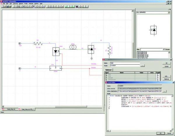
Simulator
- Thermal Models: OptiSPICE includes thermal macro models that allow you to simulate the thermal behavior of your devices, ensuring accurate results.
- Electrical Component Support: The software supports a wide range of electrical components, such as diodes, transistors (BJTs, MOSFETs), and optical components, including laser diodes, optical fibers, and photodiodes.
- Integrated Optics Support: Simulation includes integrated optics, WDM optical channels, and multimode signals.
- Advanced Numerical Techniques: OptiSPICE automatically selects the best convergence algorithm for reliable simulation results.
- HSPICE Model Compatibility: Users can import external models and netlists in HSPICE format.
- BSIM3 Model Support: Allows accurate simulation of optoelectronic circuits.
- Frequency Model Implementation: The software provides precise implementation of various frequency-dependent models, including S-parameters, pole/residuum terms, and transmission line models.
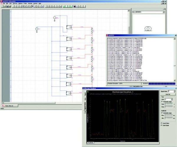
Waveform Analysis
- Waveform Viewer is a post-simulation waveform analysis tool that allows designers to view optical and electrical signal data captured by any probe placed in an OptiSPICE circuit design.
- 2D Visualization: Includes bidirectional time-domain analysis that allows for the examination of currents, voltages, optical power, magnitude, and phase measurements.
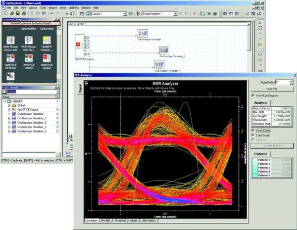
- OptiSystem Integration: With a single click, users can automatically import the same probe data into OptiSystem’s advanced post-processing environment. This enables further analysis of optoelectronic circuits, including visualization of eye diagrams, optical spectra, BER (bit error rate), and Q factor measurements.
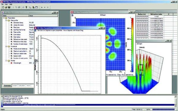
Parameter Extraction
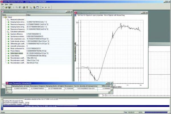
The Laser Parameter Extractor allows users to create models by extracting and fitting parameters from static and dynamic laser measurements. This means that based on real measurements (e.g. output power, wavelength, current-voltage characteristics), a simulation model of a laser can be created that accurately represents its behavior under various conditions.
The Filter Parameter Extractor allows the transformation of S-parameters (scattering matrix) into compact and efficient pole-and-residual representations. S-parameters are commonly used to describe the frequency response of high-frequency devices, and such an extractor simplifies the modeling of these devices.
The Multimode Optical Fiber Parameter Extractor includes an optical mode solver that allows users to create fiber libraries based on a user-defined refractive index profile. This allows for accurate simulation of the behavior of light waves in different types of fibers, which is crucial for the design of modern optical systems.
Video – Discover OptiSPICE
0:29 Simulation Layout
1:30 Lasers
1:38 Filter
2:30 Run the Simulation
3:39 Summary
1:58 Sub-Wavelength Aperture
OptiSPICE Applications
Below is a list of selected scientific publications, technical journals, periodicals and conference proceedings that refer to the use of OptiFDTD software. These references have been collected from internal sources, articles submitted by customers and scientific publications from Google Scholar. To the best of our knowledge, all of these works use the OptiFDTD software package. If you notice any errors, please contact us immediately at info@spectropol.pl or info@optiwave.com.
Free trial
Take advantage of the 30-day opportunity to test the Optiwave software. Sign up now!
